 |
|||
|
|
|||
|
Page Title:
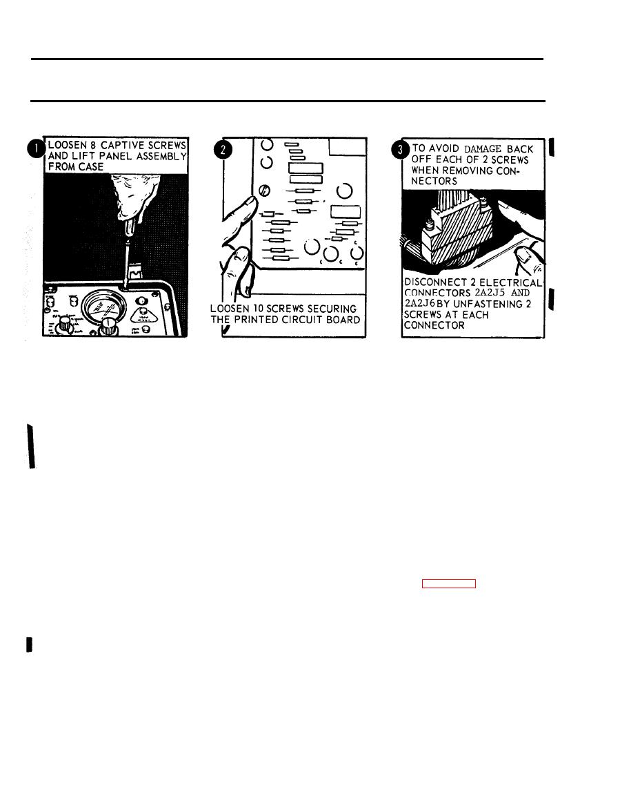
Figure 2-60. Removal of printed circuit board. |
|
||
| ||||||||||
|
|
 TM 5-6675-250-34
Table 2-1. Troubleshooting - Continued
MALFUNCTION
TEST OR INSPECTION
CORRECTIVE ACTION
CAUTION
TS 006299
b. Unfasten ten screws securing the printed circuit board to the mounting bracket and loosen the board to obtain access to
electrical connectors.
CAUTION
To avoid damage to the electrical connectors, alternately back-off each of the two attaching screws when removing the
connectors.
c. Disconnect two electrical connectors (2A2J5 and 2A2J6) by unfastening two screws at each connector.
Remove printed circuit board.
d. Depress and hold RESET switch and using an. ohmmeter, check continuity between pins 1 and 2 of switch (2A2S5).
If continuity is not present, replace RESET switch (2A2S5).
(1). Remove parts attaching the switch to the electronic control panel assembly.
(2). Unsolder the electrical leads from the bad switch and tag the electrical leads for identification.
(3). Install a good switch in the electronic control panel assembly and secure with attaching parts.
(4). Connect and solder the electrical leads in accordance with the identification tags.
CAUTION
To avoid damaging the electrical connectors, alternate tightening each of the two screws during reassembly.
(5). Install printed circuit board, but do not tighten mounting screws. Connect the two electrical
connectors and secure by tightening two screws. Fasten ten screws that secure printed circuit
board to mounting brackets.
(6). Install electronic control panel assembly in case and secure with eight captive screws.
Step 2. Inspect printed circuit board for evidence of damage or failed components.
a. Loosen the eight captive screws and lift the electronic control panel assembly from the case (Figure 2-60).
b. Unfasten ten screws securing the printed circuit board to the mounting brackets and loosen the board to obtain access to
electrical connectors.
CAUTION
To avoid damage to the electrical connectors, alternately back-off each of the two attaching screws when removing the
connectors.
c. Disconnect two electrical connectors (2A2J5 and 2A2J6) by unfastening two screws at each connector.
Remove printed circuit board.
d. Inspect printed circuit board for visual evidence of cracked circuits, corrosion, bums or
other evidence of defects.
Replace a bad printed circuit board.
CAUTION
To avoid damaging the electrical connectors, alternate tightening each of the two screws during reassembly.
(1). Install a good printed circuit board, but do not tighten mounting screws. Connect the two
electrical connectors and secure by tightening two screws. Fasten ten screws that secure printed
circuit board to mounting brackets.
2-50,
Change 1
|
|
Privacy Statement - Press Release - Copyright Information. - Contact Us |
