 |
|||
|
|
|||
|
Page Title:
Figure 2-58. Removal of electronic control unit assembly. |
|
||
| ||||||||||
|
|
 TM 5-6675-250-34
Table 2-1. Troubleshooting - Continued
MALFUNCTION
TEST OR INSPECTION
CORRECTIVE ACTION
TS 006296
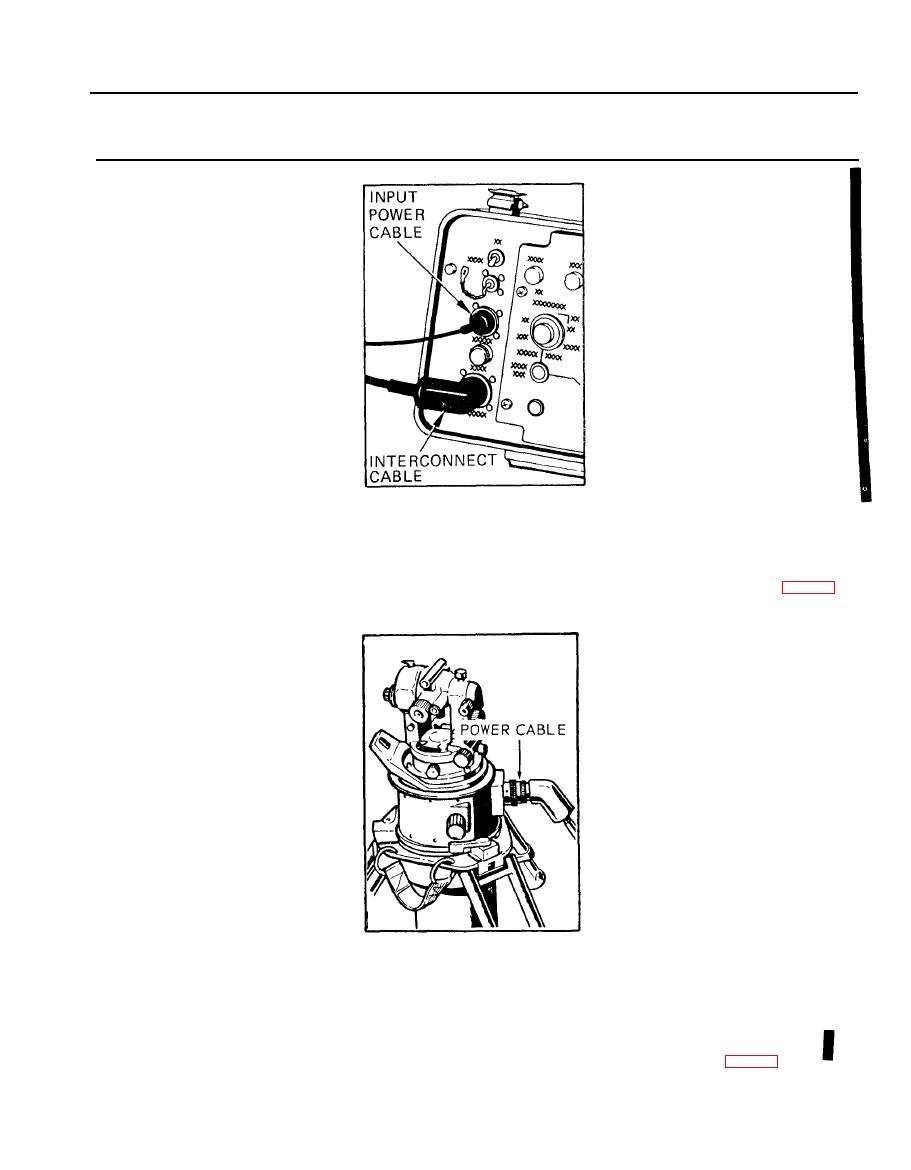
If the system operates correctly with the new ECU, report the bad ECU to the next higher level of main-
tenance.
Step 3. Check for a defective GRU.
Replace existing GRU with a GRU that is operable, by disconnecting and connecting power cables (fig. 2-59).
TS 006298
If the system operates correctly with the new GRU, report the bad GRU to the next
higher level of maintenance.
10. RESET CIRCUIT INOPERATIVE WHEN RESET SWITCH IS PRESSED
Step 2. Check for defective RESET switch (2A2S5).
a. Loosen the eight captive screws and lift the electronic control panel assembly from the case (fig. 2-24).
Change 1
|
|
Privacy Statement - Press Release - Copyright Information. - Contact Us |
