 |
|||
|
|
|||
|
Page Title:
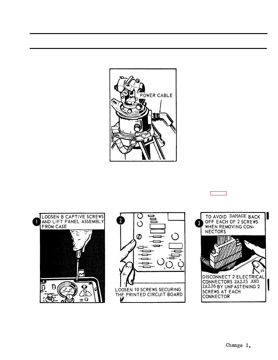
Figure 2-46. Gyroscopic reference unit power cable. |
|
||
| ||||||||||
|
|
 TM 5-6675-250-34
Table 2-1. Troubleshooting - Continued
MALFUNCTION
TEST OR INSPECTION
CORRECTIVE ACTION
T S 006285
If the system operates correctly with the new GRU, this indicates the original GRU was bad.
Report a bad GRU to the next higher level of maintenance.
Step 2. Inspect printed circuit board for evidence of damage or failed components.
a. Loosen the eight captive screws and lift the electronic control panel assembly from the case (fig. 2-47).
CAUTION
TS 006286
b. Unfasten ten screws securing the printed circuit board to the mounting brackets and loosen the
board to obtain access to electrical connectors.
CAUTION
To avoid damage to the electrical connectors, alternately back-off each of the two attaching screws when removing the
connectors.
2-37
|
|
Privacy Statement - Press Release - Copyright Information. - Contact Us |
