 |
|||
|
|
|||
|
Page Title:
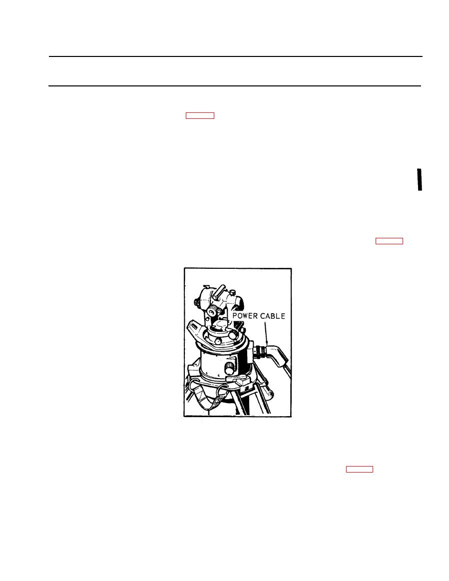
Figure 2-34. Gyroscopic reference unit power cable. |
|
||
| ||||||||||
|
|
 TM 5-6675-250-34
Table 2-1. Troubleshooting - Continued
MALFUNCTION
TEST OR INSPECTION
CORRECTIVE ACTION
(7). Press the anti-backlash setting tool into the index hole of the lower gear half and relax the
thumb and index finger.
(8). Connect the gearbox assembly electrical cable connector to the female receptacle on thegearhox
housing connector (fig. 2-33). Rotate the cable connector mounting screws in the clockwise
direction, being careful to alternate between the two screws after (2 to 3 turns).
(9). Place the cable between the gearbox assembly mounting pads, so that it will be under the
gearbox when the gearbox is in final position.
(10). Rotate the follow-up shaft to the extreme clockwise position by turning the theodolite mounting
plate.
(11). Install the gearbox assembly through the access hole and place it so that tbe mounting screw
holes are lined up.
(12). Apply sealant primer, MIL-S-22473, Grade T, Form R, to the threads, and allow to air dry.
Apply a small amount of thread locking sealant, MIL-S-46163, Grade N, Type II, to the
first few threads. Install the gearbox mounting screws, but do not tighten.
(13). Press the gearbox assembly against the index pins on the inner mounting pads and tighten the
mounting screws while maintaining the gearbox position.
(14). Remove the anti-backlash setting tool from the indexing hole.
(15). Install the gearbox assembly access cover and main connector housing screws. Secure each cover
with ten screws.
Step 2. Check for defective gyroscopic reference unit (GRU).
Replace existing GRU with a GRU that is operable, by disconnecting and connecting power cables (fig. 2-34).
TS 006273
If the system operates correctly witb the new GRU, this indicates the original GRU was bad. Report a
bad GRU to the next higher level of maintenance.
Step 3. Inspect printed circuit board for evidence of damage or failed components.
a. Loosen the eight captive screws and lift the electronic control panel assembly from the case (fig. 2-35)
Change 1,2-27
|
|
Privacy Statement - Press Release - Copyright Information. - Contact Us |
