 |
|||
|
|
|||
|
Page Title:
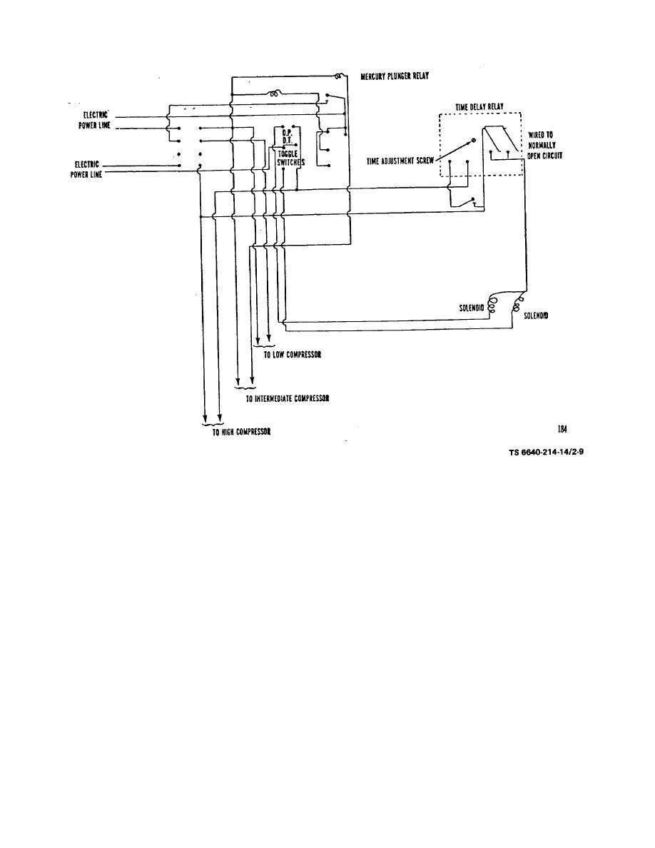
Figure 2-9. Wiring Diagram for Channel Point Apparatus. |
|
||
| ||||||||||
|
|
 TM 5-6640-214-14
Figure 2-9. Wiring Diagram for Channel Point Apparatus.
c. Compressed Air Lines. The compressed air lines on the cabinets are connected by means of union couplings or,
when necessary, by flexible metal braided hose to provide a continuous flow of compressed air to all parts of the
laboratory. After all cabinets have been connected, the compressed air lines are connected to the air compressor.
d. Water Lines. The water lines of the cabinets are connected by means of union couplings or, when necessary, by
flexible metal braided hose to provide a continuous flow of water to all parts of the laboratory. After all cabinets have
been connected, the water lines are connected to any suitable source of water available to the laboratory.
e. Drain Lines. The drain lines on the cabinets are connected by means of union couplings or, when necessary, by
flexible metal braided hose to provide drainage required by the laboratory units. After all cabinets have been connected,
the drain lines are connected to any suitable drainage facilities available to the laboratory.
2-12
|
|
Privacy Statement - Press Release - Copyright Information. - Contact Us |
