 |
|||
|
|
|||
|
Page Title:
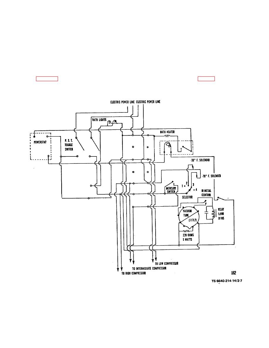
Figure 2-7. Wiring Diagram for Low Temperature Kinematic Viscosimeter. |
|
||
| ||||||||||
|
|
 TM 5-6640-214-14
(e) Starting with second cabinet to right of panelboard, connect No. 1 wire to terminal No. 2 on first
cabinet, and connect No. 2 wire of first cabinet to circuit No. 2 in panelboard.
(f) Starting with first cabinet on right of panelboard, connect No. 1 wire to circuit No. 1 in panelboard.
(g) Procedure for connecting wiring of the three cabinets to left of panelboard is same as for connecting
the three cabinets to the right of panel board.
(2) Low temperature kinematic viscosimeter apparatus. The low temperature kinematic viscosimeter
apparatus (para 2-23) is wired to maintain temperatures as low as 100 degrees F (-73.3 C) (fig. 2-7). Electric power for
the unit is obtained from the main 110-volt electric line within the laboratory.
Figure 2-7. Wiring Diagram for Low Temperature Kinematic Viscosimeter.
2-10
|
|
Privacy Statement - Press Release - Copyright Information. - Contact Us |
