 |
|||
|
|
|||
|
Page Title:
Adjustment of Entrance and Exit Time Delays |
|
||
| ||||||||||
|
|
 TM 5-6350-262-14/5
NAVELEX 0967--466-9050
TO 31S9-4-38-1
7-22. Adjustment of Entrance and Exit Time Delays
(5)
1/8 X 2 flat blade screwdriver from Tool Kit,
TK105G.
a. General. The following procedure may be used to
adjust the entrance and exit time delays following initial
installation of the equipment or at any time a change in time
c. Procedure. Perform steps (6), (25), (26), (28), and
delay is required after the system is placed in operation.
(29) only if the control unit is in use in an operating system.
Measurement and adjustment of the exit time delay is
dependent on knowing the duration of the entrance time delay.
(1) Turn operating mode switch to TEST/RESET.
Always adjust or measure the entrance time delay first before
(2) Unlock and open door.
proceeding with the exit time delay.
(3) Pull out door tamper switch plunger to the
alarm bypass position.
NOTE
(4) On newly installed equipment, connect all
orange jumper wires between terminals 1, 2, and 3 on
If the control unit is operating in a
terminal boards A through E, and between terminals 8 and 9
system, it will be necessary to utilize the
on terminal board S.
intrusion input from one sensor and to
(5) Turn operating mode switch to SECURE.
render Audible Alarm BZ-204 ( )/FSS-9
(V) inoperative during the adjustment
(6) Install a jumper wire between terminal 4 (+ 5
procedure to prevent false alarms.
volts dc) and terminal 1 (alarm output) of terminal board L2.
Notify applicable security personnel.
See figure FO-2. This action will ensure a 5volt no-alarm
output signal to Audible Alarm BZ-204 ( )/FSS-9 (V) under all
operating conditions during the adjustment procedure.
b. Test Equipment Required.
(7) Adjust TS352B VOM controls to measure 20
volts dc.
(1)
VOM, TS352B.
(8) Place POWER switch to ON.
(2)
Jumper wire, 4-inch, 6 spade lugs.
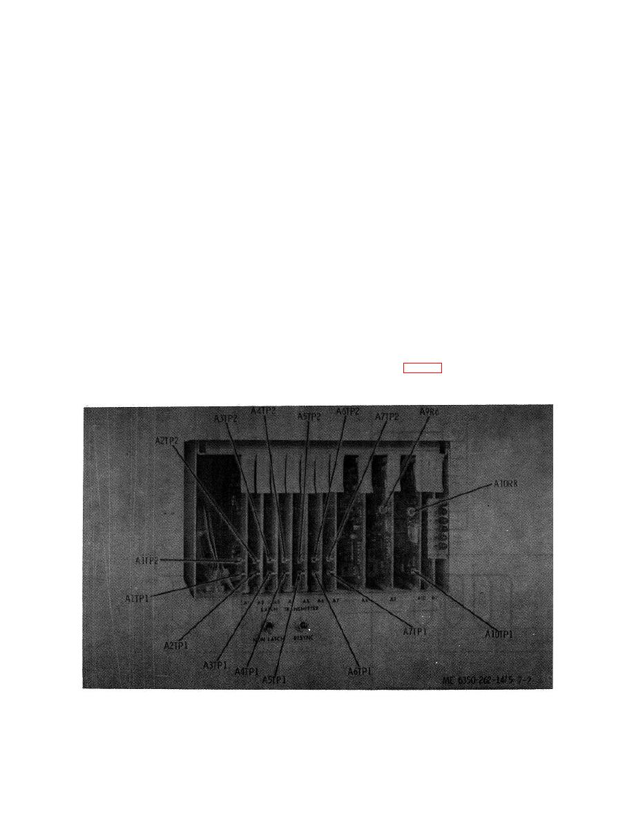
(9) Connect TS352B VOM positive lead to test
(3)
Stopwatch.
point A1OTP1 (fig. 7-2). Connect negative lead to ground.
(4)
3/16 X 4 flat blade screwdriver from Tool Kit,
The meter should indicate approximately 20 volts dc.
TK105G.
Figure 7-2. Status processor test point locations.
7-12
|
|
Privacy Statement - Press Release - Copyright Information. - Contact Us |
