 |
|||
|
|
|||
|
Page Title:
Figure 2-1. Typical CPS Installation |
|
||
| ||||||||||
|
|
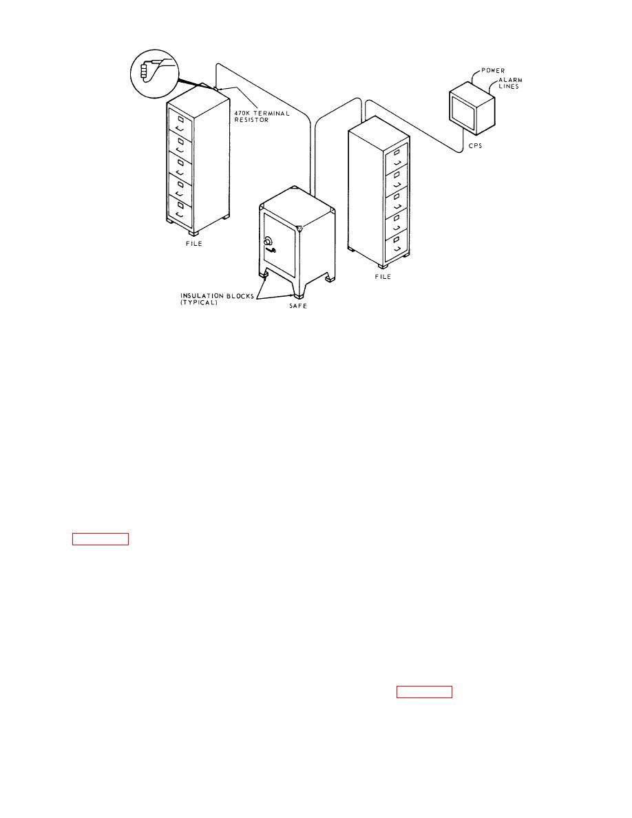 Figure 2-1. Typical CPS Installation
2-5. Connecting Power and Alarm Wiring
The positive lead of the +20 VDC power line pair is connected to TB1-7 and the return to TB1-8. Connect the
capacitance alarm output to TB1-1 and -2 and the tamper alarm to TB1-5 and -6. The two alarm returns are normally
jumpered together between TB1-2, -3, 4, and -5. The jumpers can be removed if separate alarms are desired.
2-6. Connecting the Sensor Cable
Ensure that the 470K ohm resistor is removed from TB2-1 and -2. Install insulated lugs on the center conductor and
shield of the cable. Connect the center conductor to TB2-1 and the shield to TB2-2. Connection of the sensor cable to
the protected equipment will depend upon the location and type of equipment to be protected and upon the installation
plan. Therefore, specific installation instructions cannot be given; however, the following information is furnished as an
aid in performing the installation.
2-7. General Equipment Connection Procedure
a. Figure 2-1 depicts the essential connection scheme. The separate capacitances to be protected are connected
in parallel, but with a single run of cable.
CAUTION
Splicing branches is not permissible since this destroys tamper protection.
b. All protected equipment must be insulated from ground. It is recommended that the mounting blocks be used at
all times (4 per unit).
c. Only the center conductor of the sensor cable is connected to the equipment to be protected. The outer
conductor must be insulated from the equipment and the center conductor.
d. A secure, low-resistance connection must be made to each item of equipment, since loose connections will
cause false alarms. One method of making such connections is shown in figure 2-2. A section of the outer cable
covering is cut away and an opening in the braid is made with a pointed tool. About an inch of the center insulated
conductor is drawn
2-2
|
|
Privacy Statement - Press Release - Copyright Information. - Contact Us |
