 |
|||
|
|
|||
|
Page Title:
Section IV. INSTALLATION ALIGNMENT |
|
||
| ||||||||||
|
|
 TM 5-6350-262-14/1
NAVELEX 0967-LP-466-9012
TO 31S9-4-36-1 Chg 2
The RANGE control end of the pc board is oriented
(3) Connect black lead from the chassis
toward the transmit transducer (white dot) and the Q1,
ground to its respective terminal (BLK) on the pc board.
Q2 component end of the pc board is oriented toward
e. Lead Connections. Connect the cable leads to
the transmit transducer (white dot) and the Q1, Q2
the processor and the transceiver screw type terminal
component end of the pc board is adjacent to the
strips in accordance with the configuration used, as
receiver transducer (blue dot). When the pc board is
shown in interconnecting data in figure FO-1.
secured in place, the RANGE control will be positioned
approximately midway between the ends of the
NOTE
enclosure.
(1) Connect the transmit transducer (white
For transceivers served by a single
dot) red and blue leads to their respective terminals
processor, all transmit transducers are
adjacent to the RANGE control.
parallel connected in one circuit, all the
(2) Connect the receiver transducer (white
receiver transducers are parallel connected
dot) red and blue leads to their respective terminals
in another circuit in both the processor and
adjacent to the receiver transducer.
the transceivers are all connected in series.
Section IV. INSTALLATION ALIGNMENT
2-17. General
Double the approximate run distance to
each unit to account for completing the
The procedures for alignment after installation are
tamper loop.
outlined in the following paragraphs.
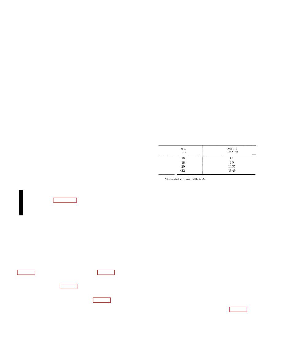
Table 2-3. Wire Resistance Per 1000 Feet
NOTE
The processor provides a synchronizing
output (terminal 7 of TB2) for connection to
any Processor, Passive Signal Ultrasonic
MX-9443( )/FSS-9(V) that might be operating
in the area protected by the processor and
transceiver. This output positions a band-
reject region in the Processor, Passive
Signal Ultrasonic MX-9443(
)/FSS-9(V)
(4) Remove the enclosure cover of each
passband to eliminate interference from the
unit (one at a time) and verify that the meter reading
ultrasonic transmission of the processor
goes to infinity (open circuit). The switch should open
and the transceiver.
Synchronization of
with no less than 1/8 inch nor more than inch of cover
processors (para. 2-19) is necessary if two
displacement.
If the switch fails to meet these
or more processors are operating in a single
requirements report malfunction to direct support
building. REASON: Reduce possibility of
(intermediate) maintenance. Pull the tamper switch
intersensor interference.
plunger out and verify that the continuity is restored and
the resistance approximates that of the tamper circuit.
2-18. Equipment Test and Final Adjustment
Fasten the cover to the enclosure and again verify that
The equipment is now ready to be checked for tamper
the continuity is complete and the resistance
circuit protection and excessive noise and walk tested
approximates that of the tamper circuit.
with all the transceivers connected and the RANGE
(5) Repeat (4) above for each of the
control on each set to the appropriate level.
enclosures.
(6) To simulate the cover on the processor
a. Tamper Circuit Test. This test involves the use
enclosure use a straight edge across opposite sides of
of two men; one to monitor the multimeter and the
the enclosure to depress the tamper switch plunger.
second to move from unit to unit and verify the switch
Verify that the continuity is complete and the resistance
operation and plunger travel.
approximates that of the tamper circuit.
(1) Remove the cover from the processor
(7) Remove the multimeter test leads and
reconnect the temporarily removed lead to terminal 5 of
out to complete the circuit in this enclosure.
TB1.
(2) Temporarily remove the lead from
b. Noise Test. This test is essentially a repeat of
terminal 5 of TB 1 (fig. 1-1) that goes to the J-SIIDS
the noise test procedure performed in the preliminary
control unit.
adjustment, section III except that all transceivers are
(3) Connect a multimeter (AN/USM-210)
connected and operating.
between terminals 2 and 5 of TB1 (fig. 1-1). With the
(1) Connect the multimeter (AN/USM-210)
covers secured to all the enclosures and the tamper
positive lead to the NOISE test point (fig. 1-1) and the
switch plunger of the processor pulled out the continuity
negative lead to the REFERENCE test point in the
should be approximately that as indicated in table 2-3.
processor. Set the multimeter to read A.C. and the
NOTE
range selector switch to 2.5V.
Approximate resistance per 1000 feet for
various wire sizes is given in table 2-3.
Change 2 2-10
|
|
Privacy Statement - Press Release - Copyright Information. - Contact Us |
