 |
|||
|
|
|||
|
Page Title:
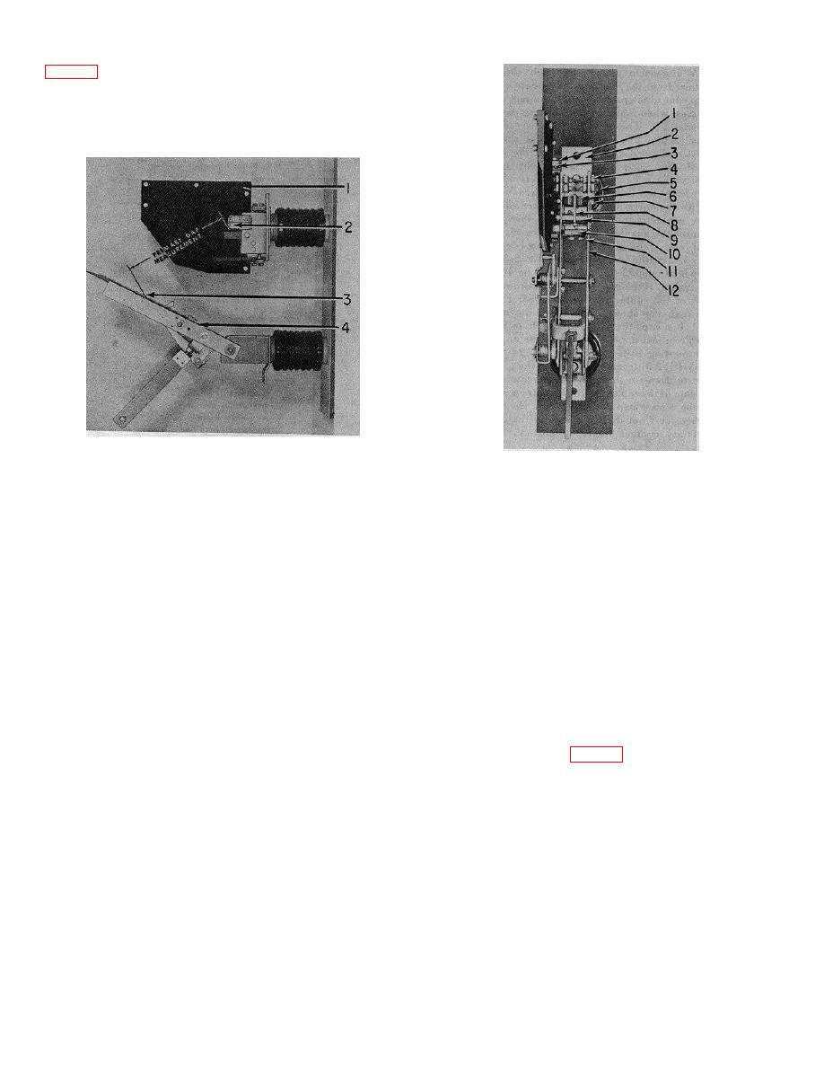
Figure 2-7. Unit pole fully open |
|
||
| ||||||||||
|
|
 adjustment of the upper stop. Move shims and washers
from the top to the bottom of the stop (or the reverse) as
required. Adjust the stops at both ends of the main shaft
the same amount to keep them balanced.
1,
Arc chute mounting bolts
1.
Arc chute
2.
Upper terminal
2.
Stationary primary contact finger
3.
Shims
3.
Primary blade stop
4.
Primary contacts
4.
Primary blade
5.
Contact bolts
6.
Arcing contact fingers
Figure 2-7. Unit pole fully open.
7.
Contact bolt
8.
Movable arcing contact fingers
(4) Primary and arcing contact alignment.
9.
Tube spacer
Close the primary blades 112, fig. 2-81 slowly using tile
10.
Guide block
maintenance handle.
Note the engagement of the
11.
Buffer block bolts
primary contacts (4), arcing contact fingers 1 (and 8), and
12.
Primary contact blades
the guide block ( 10). The blades should center around
the guide block without hearing heavily on either side.
Figure 2-8. Contact arrangement.
They should also be centered in the primary and arcing
contact fingers. If the blades press hard against the sides
(5) Arc chute alignment. The arc chute must
of the guide block, loosen the two bolts (II) holding the
be positioned to allow entry of the auxiliary blade to latch,
block. Again check the contact alignment. If the contacts
are properly aligned, reposition the guide block and
and finally to release the auxiliary blade at the proper
time. Slowly close the contact arm and check the entry of
tighten the bolt. If the contacts are not in alignment,
the auxiliary blade (7, fig. 2-5) into the arc chute. The
loosen the bolts holding the top insulator and position the
blade should enter smoothly and be in the center of the
insulator to center the contacts. After securing the
opening. If the blade scrapes heavily on the sides of the
insulators, reposition the guide blocks and tighten the
bolts. Be certain the insulator is moved only in a
chute, loosen the
horizontal direction. Vertical displacement may cause
misalignment of the auxiliary blade contacts.
2-7
|
|
Privacy Statement - Press Release - Copyright Information. - Contact Us |
