 |
|||
|
|
|||
|
|
|||
| ||||||||||
|
|
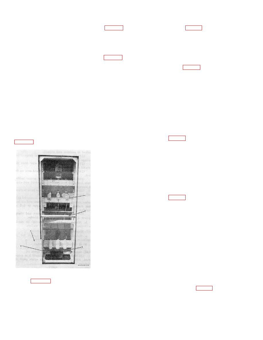 (7) Take the 50 foot cable (1, fig. 2-3)
is a removable cover (5 fig. 2-4) over the trap door (3)
provided for 115 VAC 60 cycle service and feed the free
for cable entrance from under the trailer. Loosen bolts
end down through the trap door under the right cabinet.
and remove this cover. Loosen bolt and raise trap door
Connect it to a 115 VAC 60 cycle power supply. The
(3) of trailer bed.
other end of this cable is connected to OITB-1 and 2
which is located in the lower right side of the left section
(4) Remove the primary cable from its reel
behind a plate that covers the wiring trough. (fig. 2-17).
mount on rear of trailer. Feed one end of this cable up
Close both rear doors.
through trap door (3) and into the cable entrance of the
high voltage cabinet. (fig. 2-4) This cable goes all the
(8) The trailer now has 115 volt service,
way up to the top and is connected to the connections
and the heaters and lights should be turned on when
(1}) of the load break switch. Support cable, using
substation is both in service or out of service. This
separators (2) provided in cabinet.
eliminates moisture within all enclosures. The heater
and light switch is located on the left side wall of the
CAUTION
main breaker section. (fig. 2-13.)
Before primary cable connections are
made, the conductors should be
e.
Connecting Primary Cable.
identified to indicate their phase
(1) Remove the upper and lower rear
relationship
with
the
switch
panels of the high voltage cabinet.
connections.
Make
sure
all
connections are tight.
(2) If the heater switch has been turned on
check to see that the heater in the high voltage cabinet
(5) The fourth conductor is connected to the
is working. If it is not, see Trouble Shooting Section,
ground lug. (4, fig. 2-4.)
(6) Replace upper and lower rear panels.
(7) The other end of the primary may be
connected at the source. Care must be taken to keep
the phase relationship the same as in the high voltage
cabinet.
(8)
Feed the output cables up
through the trap doors to the low voltage cabinet.
Connect these cables as the situation dictates to the
feed breakers. (fig. 2-3) Support cables so the stress is
not on the connection.
CAUTION
Before feeder cable connections are
made, the conductors should be
identified to indicate their phase
relationship
to
the
breaker
connections. When connections are
made, make sure they are tight.
(9))
The output ends of the feeder
cables are connected as the situation or installation
dictates.
Figure 2-4. Rear view of high voltage cabinet, panel
(10)
If the removable links have
removed.
been removed, the main breaker is the only one used.
KEY to figure 2-4
'The feeder cable is connected directly to the main
1.
Load break switch primary connectors
breaker output connectors (3, fig. 2-3).
2.
Cable separator and support
3.
Trap door
(11 )
When all feeder cables have
4
Ground( lug
been connected and are tight, close rear doors. The
5.
Bottom cover
trailer substation unit is ready for service.
(3) The bottom of the high voltage cabinet
2-7
|
|
Privacy Statement - Press Release - Copyright Information. - Contact Us |
