 |
|||
|
|
|||
|
Page Title:
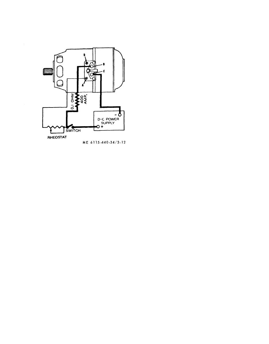
Figure 3-12. Electrical connection for running-in brushes |
|
||
| ||||||||||
|
|
 NOTE
NOTE
Instead of running the generator as a motor,
Record field current, frame temperature,
commutation, a n d generator speed as ap-
brush run-in may be accomplished by using a
plicable during each test procedure.
test stand to drive the generator.
(2) Without
operational warm-up, operate
(7) Remove all carbon dust with filtered,
generator with self excitation at 8000 rpm, 30 volts
compressed air.
and no load. Shunt field current shall not be less
than 0.81 amperes. Commutation must be black.
(3) With regulator connected to generator,
operate at 6500 rpm, 30 volts, and 300 amperes
until frame temperatures show no more than 2.0F.
(1.1C) rise in five minutes. Commutation should
not be worse than pin points along the edges of
brushes. The paralleling voltage between terminals
" D " and "E" must be within limits shown on
calibration chart (fig. 3-14). Frame temperature
must not exceed the air inlet temperature by more
t h a n 230F (110C).
(4) Operate at 5000 rpm, 30 volts, 300 am-
p e r e s for demonstrating ability to operate at
minimum speed for regulation. Shunt field current
shall not exceed 8.0 amperes. Commutation shall
be no worse than pin points along the edges of
brushes.
( 5 ) Operate at 6500 rpm (revolutions per
minute), 30 volts, and vary load from 0 to 300
amperes in increments of 100 amperes to check for
compounding. The field current must increase in
Figure 3-12. Electrical connection
load:
for running-in brushes.
(6) Reduce speed to approximately 4500 rpm.
3-16. Starter-Generator Test Procedures
operate no load and open field until frame tem-
a. General. After brushes have been properly
perature is 140F. (60C) or less. Substitute a
seated and run-in, the generator should be mounted
resistance of 1.25 ohms for regulator in the field
on a test stand having sufficient capacity to handle
circuit and adjust speed to produce 26 volts and
a 300 ampere unit. T h e test stand should be
300 amperes. Operate until speed is not over 4500
equipped with a variable drive capable of attaining
rpm with frame temperature stabilized or showing
generator speeds up to 10,000 rpm.
no more than 2.0F. (1.1C) rise in five minutes.
b. Test Equipment Required (fig. 3-13).
Commutation should not be worse than pin points
(1) The variable drive, or prime mover, for
along edges of brushes.
operating the generator should have a rating of at
( 7 ) Reconnect regulator and observe con-
least 30 horse power and a maximum speed in
nutation at 30 volts, zero amperes, 200 amperes
excess of 10,000 rpm.
and 300 amperes at speeds of 5000 and 6500 rpm.
(2) A direct current voltmeter (0 to 30 volts)
Record the worse condition of commutation and
must be available for measuring terminals voltage.
the speed at which it occurs. Commutation must
(3) A direct current ammeter (0 to 300 am-
not exceed pin points along the brush edges.
peres) must be available for measuring generator
(8) Operate at 8000 rpm, 30 volts and 300
output.
amperes. Commutation must not exceed pin points
(4) A direct current ammeter (0 to 10 am-
along the brush edges.
peres) must be available for measuring generator
(9) Remove generator from test stand and test
field current.
all circuits to ground with 200 volts A. C. rms, 60
c. Performance Tests. Performance tests shall be
cycle for a period of one minute. There shall be no
with the following
c o n d u c t e d i n accordance
grounds in any circuit.
paragraphs after brushes have been seated 100
(10) Set up a dial indicator gage on generator
percent in direction of rotation and at least 90
frame and check the commutator for eccentricity by
percent in the axial direction.
rotating the armature slowly by hand. The total
(1) Mount generator on test stand and make
indicated run-out must not exceed 0.001 inch and
connections to voltage regulator and reverse current
the bar to bar change must not exceed 0.0002 inch.
r e l a y in accordance with figure 3-13. Attach
c. Installation. Install the starter-generator (para
thermocouple to generator frame.
2-8).
3-18
|
|
Privacy Statement - Press Release - Copyright Information. - Contact Us |
