 |
|||
|
|
|||
|
Page Title:
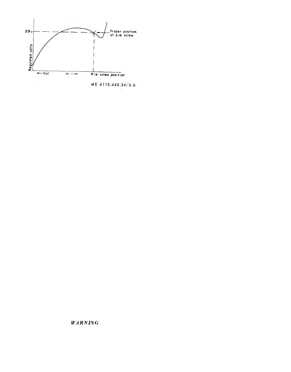
Figure 3-5. Pile screw adjustment curve. |
|
||
| ||||||||||
|
|
 terminals X1 and X2, and an ohmmeter across
terminals A1 and A2.
(2) With no voltage applied, the ohmmeter
should indicate an open circuit.
(3) Slowly increase the applied voltage until
the relay actuates (continuity indicated). The relay
should actuate when the applied voltage reaches 18
volts.
(4) Slowly reduce the applied voltage until the
relay drops out (open circuit indicated). The relay
s h o u l d drop out when the applied voltage is
decreased to between 1.5 and 7 volts.
(5) Replace relay K2 if it does not pass the
test.
c. Installation. Refer to figure 3-1 and install the
Figure 3-5. Pile screw adjustment curve.
output relay.
3-3. Reverse Current Relay (K1)
3 - 5 . Terminal Board Assembly
a. Removal. Refer to figure 3-1 and remove the
a. Removal. Refer to figure 3-1 and remove the
reverse current relay.
terminal board assembly.
b. Test. U s i n g a n o h m m e t e r , c h e c k r e v e r s e
b. Inspection. Inspect terminal lugs of all
current relay (fig. 3-1) as follows:
assemblies for corrosion. cracks or other damage.
(1) Check the resistance between APP ter-
Replace if damaged.
minal and the case (Ground). The resistance should
c. lnstallation. Refer to figure 3-1 and install the
measure approximately 90 ohms.
terminal board assembly.
(2) Check the resistance between the APP and
S W terminals, The resistance should measure
3 - 6 . Load Stud Assembly
approximately 330 ohms.
a.
Removal. Refer to figure 3-1 and remove the
( 3 ) Check the resistance between the SW
load
stud assembly.
terminal and the case (ground). The resistance
b.
Installation. Refer to figure 3-1 and install the
should measure approximately 220 ohms.
load
stud assembly.
(4) Check the resistance between the BAT and
3 - 7 . Wiring Harness
IND terminals. The resistance should measure
a. Removal. Refer to figures 1-1 and 1-2 for
approximately 6 ohms.
r e m o v i n g wiring harness. Remove plastic clips
(5) Replace reverse current relay K1 if it does
where necessary when removing the wiring harness.
not pass the tests.
b. Replacement. To replace a lead, disconnect it
b. Installation. Refer to figure 3-1 and install the
at each end and install a new lead of the same size
reverse current relay.
and number. Solder or secure as applicable all
3 - 4 . Output relay (K-2)
t e r m i n a l connections to insure good electrical
a. Removal. Refer to figure 3-1 and remove the
contact. Reinstall the plastic clips after replacing
output relay.
wiring harness.
b. Test.
(1) Connect a variable 28-volt D. C. supply to
Section II. FUEL SYSTEMS
3-8. General.
for a minimum of eight (8) hours.
Remove fuel cap and open the
The fuel system maintenance consists of the fuel
discharge and return lines during
tank governor control and the governor.
welding process. Failure to observe
3 - 9 . Fuel Tank
this warning may result in serious
a. Removal. Remove the fuel tank (TM 5-6115-
injury or death.
440-20).
c. Installation. Install the fuel tank (TM 5-6115-
b. Repair. Repair the fuel tank by welding or
440-20).
brazing.
3 - 1 0 . Governor Control Assembly
a. Removal.
Before attempting to weld or braze
(1) Remove the intake manifold (TM 5-6115-
the fuel tank, steam clean the tank
440-20).
3-6
|
|
Privacy Statement - Press Release - Copyright Information. - Contact Us |
