 |
|||
|
|
|||
|
|
|||
| ||||||||||
|
|
 TM 5-6115-423-15
panel or door allowing access to the major
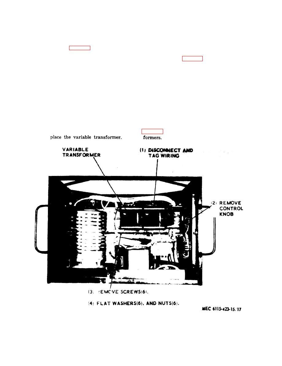
b. Removal and Installation. Refer to figure
17 to remove and install the variable trans-
component.
former.
72. Variable Transformer
a. On Equipment Test.
73. Auto Transformers
(1) Refer to figure 6 and 9.
(2) D e - e n e r g i z e load bank and connect
a. On Equipment Test.
voltmeter to terminals # 1 and #4.
(2) De-energize load bank and connect
(3)
Energize load bank. Reading should
voltmeter to terminals H1 and X2.
be of 240 volts AC.
(3) Energize load bank with 240/416
(4)
D e - e n e r g i z e load bank and connect
volts AC.
v o l t m e t e r to terminals #3 and #4.
(4) Voltmeter should read 240 volts.
(5)
Energize load bank and turn the var-
(5) De-energize load bank and connect
iable control all the way counterclock-
voltmeter to X1--X2.
w i s e . The voltmeter should read 0.
(6) Re-energize load bank and voltmeter
volts. Turn the variable control gradu-
should read 120 volts AC.
ally clockwise until it is all the way
(7) If this reading is not obtained, re-
clockwise. The voltmeter
reading
place auto transformer.
should gradually increase to 240 volts
b. Removal and Installation. Refer to
AC.
(6)
If these readings are not obtained, re-
,figure 17.
Variable transformer removal and indstallation.
32
|
|
Privacy Statement - Press Release - Copyright Information. - Contact Us |
