 |
|||
|
|
|||
|
Page Title:
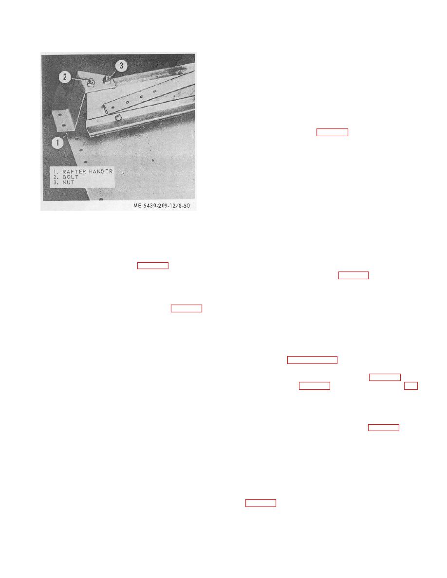
Figure 8-50. Rafter hanger installed. |
|
||
| ||||||||||
|
|
 TM 5-5430-209-12
section, since no further assemblies are made on it.
Keep the last deck section separated from all other
sections until it is installed in the deck.
f. Assembling Center Deck Plate. The center deck
plate consists of two semicircular, flat, steel plates. The
two plates are joined together by bolted lap joints. The
plate covers the umbrella support. The outer
circumference bolting circle laps over the inner edge of
the deck sections.
(1) Lay plate (1, fig. 8-56), numbered side up,
on tank bottom. Place blocking under lap seam of the
plate.
NOTE
Make sure blocking does not block entrance to
the bolt holes.
(2) Place a bolt channel under the lap seam of
the plate. Insert 1/2-by-11/4 -inch bolts (2) through all
except the last bolt hole on the inner and outer
circumference of the plate and channel.
Figure 8-50. Rafter hanger installed.
(3) Remove the blocking and place a bolt
retaining board under the bolt channel.
(17) Turn the deck section over with trussed
(4) Install strip gasket (3) along the full length of
rafters resting on the tank bottom. Remove all finger
the lap seam. Allow a 1/2 -bolt hole overlap at each
tightened nuts installed on the bolts.
end.
(18) Install strip gasket (1, fig. 8-48) along the
(5) Install steel recessed washer, cup side down,
full length of the right and left seams. Allow a 1-bolt
and nut on each of the bolts (2, fig. 8-56) protruding
hole overlap at each end of the seam.
through the plate. Be sure the rounded head of the nut
is against the washer. Tighten the bolts.
d. Assembling Special Deck Sections.
(6) Raise center deck plate assembly (5, fig. 8-
(1) Install pressure vacuum valve (2, fig. 8-54)
54) to the deck before the deck sections are completely
on the plate of the first deck section to be installed.
installed.
(2) Insert /2 by 1/2 inch bolts through 2-bolt hole
8-18. Installation of Deck Sections
channels. Work through the 8-inch hole and insert the
bolts through the section. Place blocking under the bolt
a. Scaffold for Deck. Install a scaffold around the
heads to hold them in place during installation of the
tank about 3 feet below the top chime of the third ring
gasket.
staves. Refer to paragraph 3-8 and install the scaffold.
(3) Install a 16-hole gasket over the bolts.
b. Gin Pole.
(4) Install a pressure vacuum valve over the
(1) To install the deck section (3, fig. 8-53),
bolts.
position the pole (1, fig. 8-32) with the foot spike (1, fig.
(5) Install nuts on the bolts and tighten.
8-33) placed in a bolthole in the bottom chime of the
(6) Remove the blocking used in step (2) above.
third ring staves. Follow the procedures in paragraph 8-
(7) Install pressure vacuum valve (2) on a hatch
14e.
deck plate (4). Follow the procedures in steps (1)
(2) Erect the pole at every vertical seam in the
through (6) above.
third ring. Install a temporary bracket (3, fig. 8-32) at
(8) Install blind hatch flange (3) on three hatch
every seam not occupied by a scaffold bracket.
deck plates (4). Use the same bolts, channels, and
(3) Install the pole on the vertical seam at the
gasket as in steps (2) and (3) above. Follow the above
point selected for the installation of the first deck
procedures.
section. Replace the bolt in the bottom chime each time
(9) The level indicator plate (6) is installed with
the pole is moved.
level indicator fitting (7) as received.
c. Adjusting Center Support. Check and adjust the
center support before installing the deck sections. The
e. Assembling Remaining Intermediate Sections.
distance from the top of the center support base plate
There are 35 intermediate deck sections assembled with
(6, fig. 8-51) to the top of the rafter support clips should
trussed rafters and strip gaskets. The trussed rafters are
be 22 feet 1-7/16 inches. Raise or lower the support as
placed under the right lap seams only. The above
required.
procedures do not apply to the last deck
8-31
|
|
Privacy Statement - Press Release - Copyright Information. - Contact Us |
