 |
|||
|
|
|||
|
Page Title:
CHAPTER 8 ERECTION INSTRUCTIONS FOR THE 10,000-BARREL CAPACITY TANK |
|
||
| ||||||||||
|
|
 TM 5-5430-209-12
CHAPTER 8
ERECTION INSTRUCTIONS FOR
THE 10,000-BARREL CAPACITY TANK
Section I. ASSEMBLY AND INSTALLATION OF TANK BOTTOM
8-1.
Center Support Base
a. General. The center support base consists of a
short, tubular, support column mounted on a circular,
flat, steel plate. The support column is held in position
on the steel plate by radially extended, vertically
mounted and welded, steel gussets. The two halves of
the tank bottom adapter plate are bolted to the center
support base.
b. Installation.
(1) Drive all grade stakes below the surface
of the foundation. Backfill and tamp the resulting hole.
(2) Locate center support base blocking (2,
1.
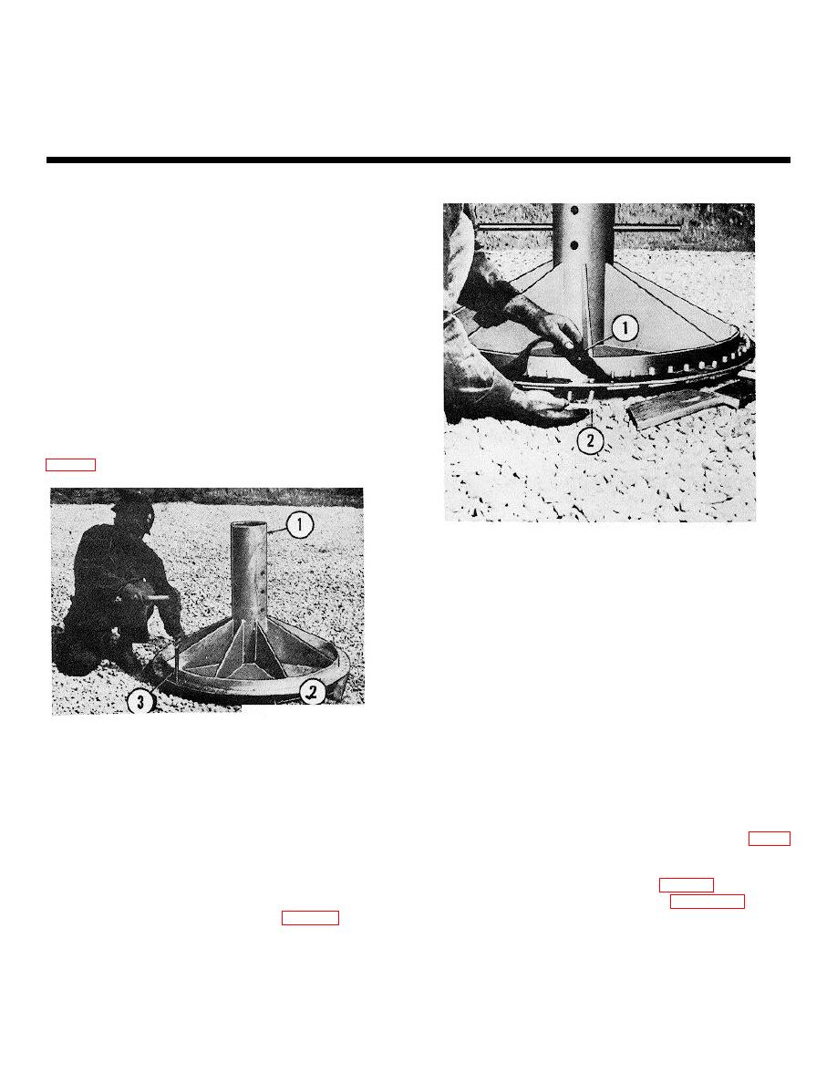
STRIP GASKET
2.
TWO-BOLT HOLE CHANNEL
ME 5430-209-12/8-2
Figure 8-2. Installing channels, bolts, and gaskets
on the center support base.
(5) Insert two l/2-by 112-inch bolts in the 2-
bolt hole channel (2).
CAUTION
1.
CENTER SUPPORT BAE
To prevent damage to the gasket, do
1.
CENTER SUPPORT BASE
not use a sharp-edged tool or pipe to
2.
BLOCKING
force the gasket over the bolts. Use a
3.
DRIFT PIN
well-rounded, smoothmouth tool.
ME 5430-209-12/8-1
Figure 8-1. Center support base.
(6) Insert the channel assembly through
center support base plate and gasket as shown in figure
8-2.
(3) Position center support base (1) over the
center grade stake. Make sure blocking (2) does not
(7) Remove blocking (2. fig. 8-1) and insert
block the entrance to the boltholes.
bolt retaining boards as shown on figure 8-3. These
boards will prevent movement of bolts when center
(4) Place strip gaskets (1, fig. 8-2) around
adapter plate is installed.
bolt circle of center support base. Where there is a
break in the gasket, overlap the joint two boltholes.
(8) Apply sealing compound
to
gasket
Make a beveled cut squarely across the second bolthole
overlap joints to insure a tight connection.
in the gasket. This will insure a smooth joint where the
gasket overlaps.
8-1
|
|
Privacy Statement - Press Release - Copyright Information. - Contact Us |