 |
|||
|
|
|||
|
|
|||
| ||||||||||
|
|
 TM 5-5430-209-12
6-18. Manhole Air Intake
manhole dome (1) so that the inner ring tits outside the
bolt circle of the dome.
a. General. The manhole air intake is used on
(5) Place dust restrictor over the assembled screen
water storage tanks and installed on the manhole dome.
and rings.
It consists of the following components: insect screen,
(6) Working through the opening in the dust
inside screen ring, outside screen ring, dust restrictor,
restrictor, install sleeve spacers between the restrictor
manhole cover, flange bolts, and sleeve spacer.
and manhole dome at alternate bolt holes. Aline the
b. Installation.
holes.
(1) Remove nuts (4, fig. 6-18) and manhole cover
(7) Install the manhole cover on the dust restrictor.
(3) from dome (1). Remove the bolts (2) and gasket.
Insert flange bolts through all holes from the top side.
(2) Wrap the insect screen around the outside of
Install a nut on each bolt and tighten securely.
the inside screen ring. Join the ends of the screen with
6-19. Water Drawoff Valve
copper wire weave.
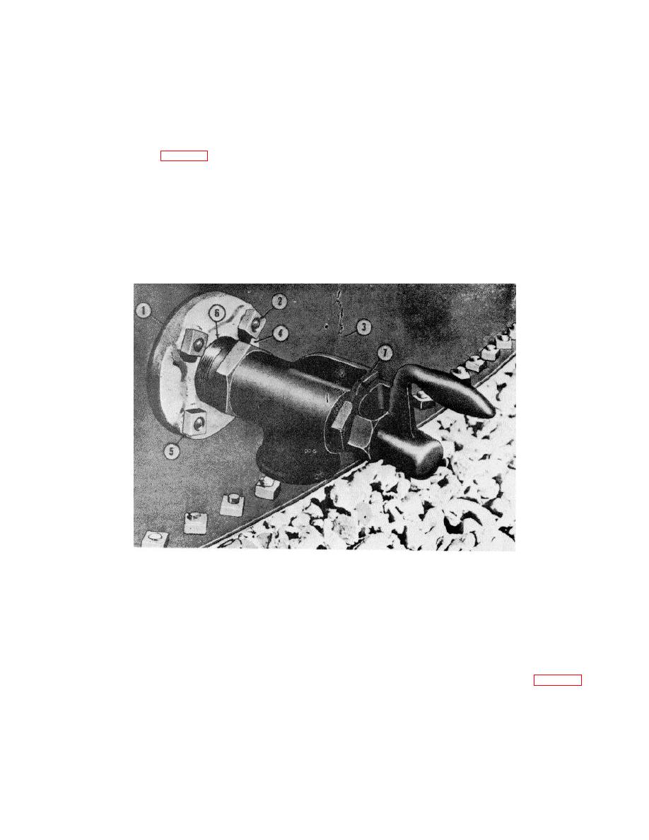
a. General. The water drawoff valve (7, fig. 6-
(3) Install an outside screen ring around the insect
21), installed in special stave (3), is a 2-inch antifreeze-
screen at the top and bottom. Make sure the screen is
type valve. It is used to drain water from petroleum
properly positioned on the inside ring. Tighten the bolts
storage tanks. A 2-inch flange set (4) and 11/2-inch
and nuts on the outside rings.
steel nipple (6) are used with the valve.
(4) Install the assembled screen and rings on
ME 5430-209-12/6-21
1. GASKET
2. BOLT
3. STAVE
4. OUTSIDE FLANGE HALF
5. NUT
6. STEEL NIPPLE
7. WATER GRAWOFF VALVE
Figure 6-21. Water drawoff valve installed.
b. Installation
(b) Cut fort 1-hole gaskets (1, fig. 6-22) from
(1) Flange Set
strip gasket. Place one gasket under the head of each
(a) Dissemble flange set by removing nuts and
bolt (2).
bolts
6-23
|
|
Privacy Statement - Press Release - Copyright Information. - Contact Us |
