 |
|||
|
|
|||
|
Page Title:
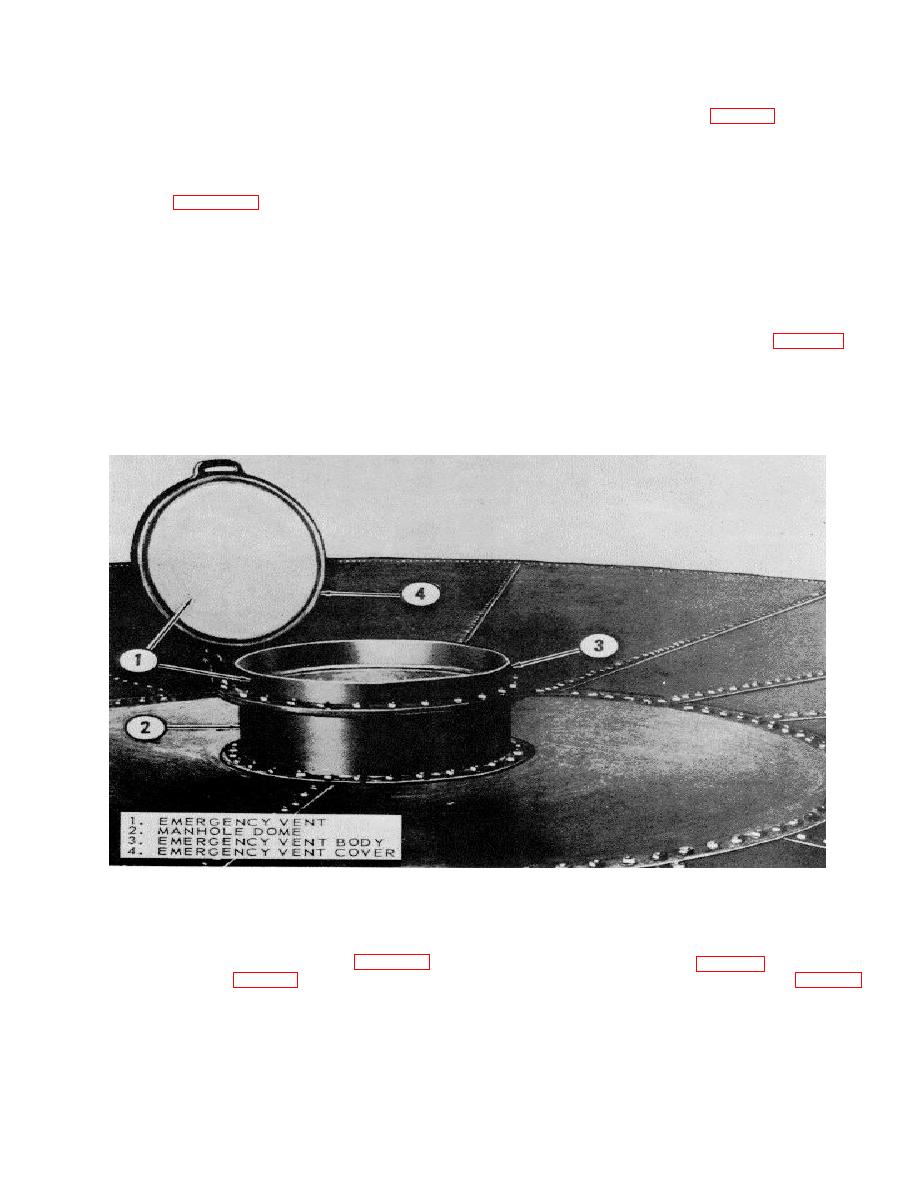
Figure 6-20. Emergency vent installed |
|
||
| ||||||||||
|
|
 TM 5-5430-209-12
(1) Place assembled ladder where it is convenient
(2) Starting at the third hole from either end of the
to the pressure vacuum valve (8, fig. 6-19) at the outer
sections, place ladder steps (3) underneath the sections
perimeter of the deck.
with step angles all facing in the same direction. Aline
(2) Lift the ladder and set end bolt holes of braces
the steps between sections, and install 1/2 by 1-inch
(5 and 6) over bolts in bottom chime of the staves.
bolts (4) through sections and steps from the top side.
Mark the bolts.
Install a nut on each bolt and tighten securely.
(3) Set bolt holes of handrails (7) over bolts in the
(3) Refer to figure 6-19 and install brace (5) on
top chime of the staves. Mark the bolts.
bottom of right section (1) with the 3-hole side of the
(4) Remove nuts from the marked bolts and set
brace facing the section. Use bolt (4) and nut, but do
ladder in place over the bolts. Install nuts and tighten
not tighten. Install brace (6) on left section in the same
them securely.
manner.
(5) Tighten nuts securing braces (5 and 6) to
(4) Install handrail (7) on the top outside face of
sections (1 and 2).
each section. Secure each handrail with two bolts (4)
6-17. Emergency Vent
and nuts.
c. Installation.
a. General. The emergency vent (1, fig. 6-20) is
NOTE
installed on the manhole dome (2) of petroleum storage
Use a temporary ladder where applicable when
tanks to provide a means of venting the tanks, when
installing the access ladder.
necessary. It consists of a cast steel body (3) and a cast
steel cover (4) equipped with a lifting handle. The cover
is hinged to the body.
ME 5430-209-12/6-20
Figure 6-20. Emergency vent installed.
b. Installation. Emergency vent (1, fig. 6-20)
(2) Install emergency vent (1, fig. 6-20) over the sket
3places manhole cover (3, fig. 6-18).
and bolts in manhole dome (2). Install nuts fig. 6-18)
(1) Remove nuts (4) and manhole cover (3).
on the bolts and tighten securely.
6-22
|
|
Privacy Statement - Press Release - Copyright Information. - Contact Us |
