 |
|||
|
|
|||
|
Page Title:
Section II. ASSEMBLY AND INSTALLATION OF SIDE STAVES |
|
||
| ||||||||||
|
|
 TM 5-5430-209-12
Section II. ASSEMBLY AND INSTALLATION OF SIDE STAVES
6-8. Assembly of Side Staves
a. General. This is a single ring tank. Place all
center support ladder components and manhole dome
on the bottom before laying staves around the perimeter
of the tank foundation. This is to avoid having to lift
them over the tops of the staves later. Top and bottom
flanged edges of staves are called chimes; side edges
are called vertical seams. The staves have two rows of
bolt holes in each seam.
NOTE
Stave assemblies for petroleum and water
storage tanks are all the same except for special
fittings.
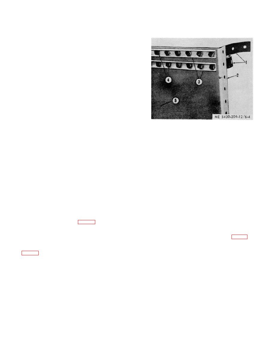
b. Layout of Staves. Five special and 15 plain
1.
STRIP GASKET
staves make up the ring.
2.
CHIME
(1) Place staves with opening and pipeline
3.
STAVE JOINT CHANNEL
connections in proper position.
4.
BOLT
(2) Lay remaining staves around the perimeter
5.
STAVE
of the bottom. Place staves with chimed side down for
convenience in preparing them for assembly. Staves
Figure 6-4. Dressed vertical seam of stave.
are laid out so each straddles a radial seam of the
bottom when installed.
(3) Place channel (3) on inside of stave (5) over
each row of boltholes.
NOTE
(4) Insert bolts (4) through stave joint channels
Staves have an offset at top and bottom. The
(3), stave (5), and gaskets (1), from the inside. Omit
top is determined by looking at the staves in a
one bolt (4) in each row of boltholes about 10 inches
vertical position from the outside. In proper
from bottom of stave and other bolts at about 2-foot
position, offsets are at the lower left and upper
intervals, so that drift-pins can be inserted to aline
left corner.
staves with one another before bolting them together.
d. Preparing Outer Edge of Tank Bottom. As no
c. Dressing Staves.
channels are used with the bolts inserted through the
(1) Each end of the chime at the offset and plain
chime (outer edge) of the bottom, it must be raised to
section must be slightly bent for ease in installing. End
provide clearance to insert and tighten the bolts for
of the chimes at the offsets (1, fig. 3-8) must be bent
installation of the staves.
inward (towards each other). End of the plain chimes
(1) Raise the chime and block it up with short
(2) are bent outward (away from each other). Bends are
lengths of 3 by 3 or 4 by 4 inch timbers (1, fig. 6-5) at
made with a few sharp blows from a hammer.
equally spaced intervals around the perimeter of the
(2) Along the right seam of each stave, as it will
bottom. Set the inner end of the blocking about 6
be put in place with the chimes out, place strip gasket
inches in from the outer edge of the chime.
(1, fig. 6-4) on the outside at each row of boltholes.
Gasket material comes in rolls and is cut to proper
length for each stave. Cut gasket material so that it
covers and projects two boltholes past the top and
bottom chimes (2).
6-4
|
|
Privacy Statement - Press Release - Copyright Information. - Contact Us |
