 |
|||
|
|
|||
|
Page Title:
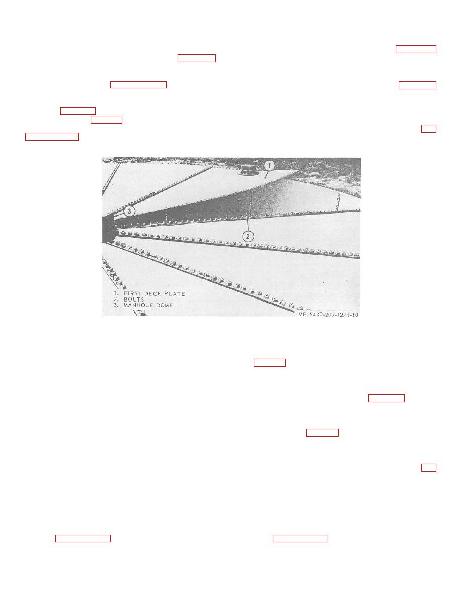
Figure 4-10. Installing last deck plate. |
|
||
| ||||||||||
|
|
 TM 5-5430-209-12
(4) Unlock and remove the jack.
3-16e and install the second deck plate.
f. Installing Intermediate Deck Plates. There are
remove and assemble gin pole components, less the
foot spike, provided in the tank tool erection set. Follow
seven intermediate plates. The special plates remaining
procedures prescribed in paragraph 3-16c.
are installed to suit field conditions. Refer to paragraph
d. Installing First Deck Plate. The first plate
3-16 d and e, and raise and install these plates.
g. Installing Last Deck Plate.
installed is one of two plates with a pressure vacuum
valve (2, fig. 3-20). The other plate with a pressure
(1) Raise last deck plate before next-to-last
vacuum valve (2, fig. 4-8) must be installed directly
plate is installed.
across from the first plate with the valve. Refer to
(2) Raise right lap seam of first plate (1, fig.
4-10). This is necessary to permit installation of the last
plate.
Figure 4-10. Installing last deck plate.
nuts on all bolts in the vertical seams. Return brackets
(3) The left lap seam of last plate slips under
and posts to the tank tool erection set. Remove gin pole
the right lap seam of first plate (1). The right lap seam
(1, fig. 3-22) after all deck plates are installed.
of last plate is placed over bolts (2) in left lap seam of
h. Installing Manhole Cover.
next-to-last plate installed.
NOTE
(4) Make necessary adjustments in deck if
last plate fails to fit properly.
If this tank is used for water storage,
NOTE
omit emergency vent (2, fig 3-24).
After all deck plates are installed,
Install manhole cover (1) after installing
check, and if necessary adjust height of
the manhole air intake
center support ladder as described In b
(1) Install a 28-bolthole gasket on the top
above.
flange of dome (3, fig. 4-10).
(5) Remove nuts temporarily installed on all
(2) Insert 1/2 by 1-inch bolts through the
bolts in the plate lap seams. Install a steel washer and
flange and gasket in that order. Gasket will hold bolts in
nut on all bolts except on bolts in top chime of staves.
place.
Install any missing nuts on chime bolts. Make sure
(3) Install 28-bolthole manhole cover (1, fig.
rounded head of nut is against the plate and/or washer.
3-24) over the bolts. Install a steel washer and nut on
all bolts. Install washer and nut as in g (5) above.
Tighten the bolts.
(6) Remove the scaffold. Install washers and
Tighten the bolts.
Section V. ASSEMBLY AND INSTALLATION OF TANK ACCESSORIES
4-18. Emergency Vent
4-19. Manhole Air Intake
Refer to paragraph 3-17 for description and installation
Refer to paragraph 3-18 for description and installation
of the emergency vent.
of the manifold air intake.
4-10
|
|
Privacy Statement - Press Release - Copyright Information. - Contact Us |
