 |
|||
|
|
|||
|
|
|||
| ||||||||||
|
|
 TM 5-5430-209-12
(4) Insert flange bolts through cover (1, fig.
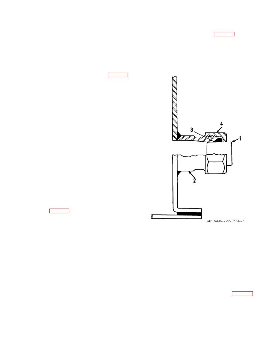
(1) Install solid plug (1, fig. 3-25), small end
324), dust restrictor, pipe sleeve spacers, and top flange
first, inside the coupling (2), Use a hammer and drift pin
of dome, in that order. Install nuts on bolts and tighten.
to drive it tight.
3-19. Access Ladder
(2) Install retainer cup (3) over plug (1);
a. General. The access ladder consists of one,
tapered face of packing should ' ear against tapered
bolted, steel angle section. The top of the ladder is
seat in coupling (21.
attached to the deck by two hand rails. Two braces
(3) Install gland nut (4) over plug (1). Take up
support the ladder at the bottom chime of a stave.
the nut carefully and tight on the coupling (2).
b. Assembly.
(1) Place access ladder rails (3 and 4, fig. 3-
24), with similar bolting legs facing each other, on top of
several pieces of blocking. The blocking should be long
enough to support both rails. Rails should be spaced
wide enough apart to install ladder step (6).
(2) Select the bottom of the ladder. Seven
steps make up the assembled section. Insert bolts (5)
through ends of step (6) and access ladder rails (3 and
4) in that order. Install a nut on each bolt, and tighten
after all nuts are installed.
(3) Install braces (7 and 8) at bottom of
access ladder rails.
(4) The leg with three boltholes near each
end of the braces is attached at the outside face of the
vertical legs of the sections.
(5) Insert a bolt through the end bolthole in
rails (3 and 4) and braces (7 and 8), in that order. Install
nuts on bolts and finger tighten bolts.
(6) Install hand rails (9) at top of access
ladder rails (3 and 4). Insert bolts through ladder rail
horizontal legs and rails, in that order. Install nuts on
bolts and tighten bolts.
c. Installation
NOTE
Use a temporary ladder when Installing the
access ladder
(1) Place assembled ladder where it is
convenient to the pressure vacuum valve at outer
perimeter of deck.
(2) Lift ladder and set end bolt holes of
braces (7, and 8, fig. 3-24) over bolts in bottom chime of
the staves. Mark the bolts.
(3) From top of the temporary ladder, mark
bolts in outer perimeter of deck covered by the hand rail
(91. Remove the access ladder. Remove nuts from the
1. PLAIN SOLID PLUG
bolts.
2. SLEEVE-TYPE COUPLING
(4) Set access ladder back over the bolts.
3. RETAINER CUP
Install nuts on bolts and tighten the bolts.
4. GLAND NUT
(5) Tighten bolts attaching braces to bottom
Figure 3-25. Plug installed
of ladder.
(6) Remove and disassemble the temporary
3-21. Water Drawoff Valve
ladder.
a General. The valve assembly consists of a
3-20. Gland Stave Plugs
'2inch bronze valve made up in a steel flange and a
a. general. The gland stave is fitted with three
gasket installed outside the tank. A one-piece flange
gland openings. When the tank is used for gasoline
elbow with gasket is installed inside the tank. The valve
storage the openings are plugged. For oil storage a
and elbow are bolted together through the side of the
steam coil is installed inside the tank, the glands being
tank.
used for the coil.
b Installation.
b Installation.
(1) Flanged elbow. The elbow (1, fig. 3-26) is
NOTE
installed inside the tank on the stave (5).
"Work inside the tank
3-22
|
|
Privacy Statement - Press Release - Copyright Information. - Contact Us |
