 |
|||
|
|
|||
|
Page Title:
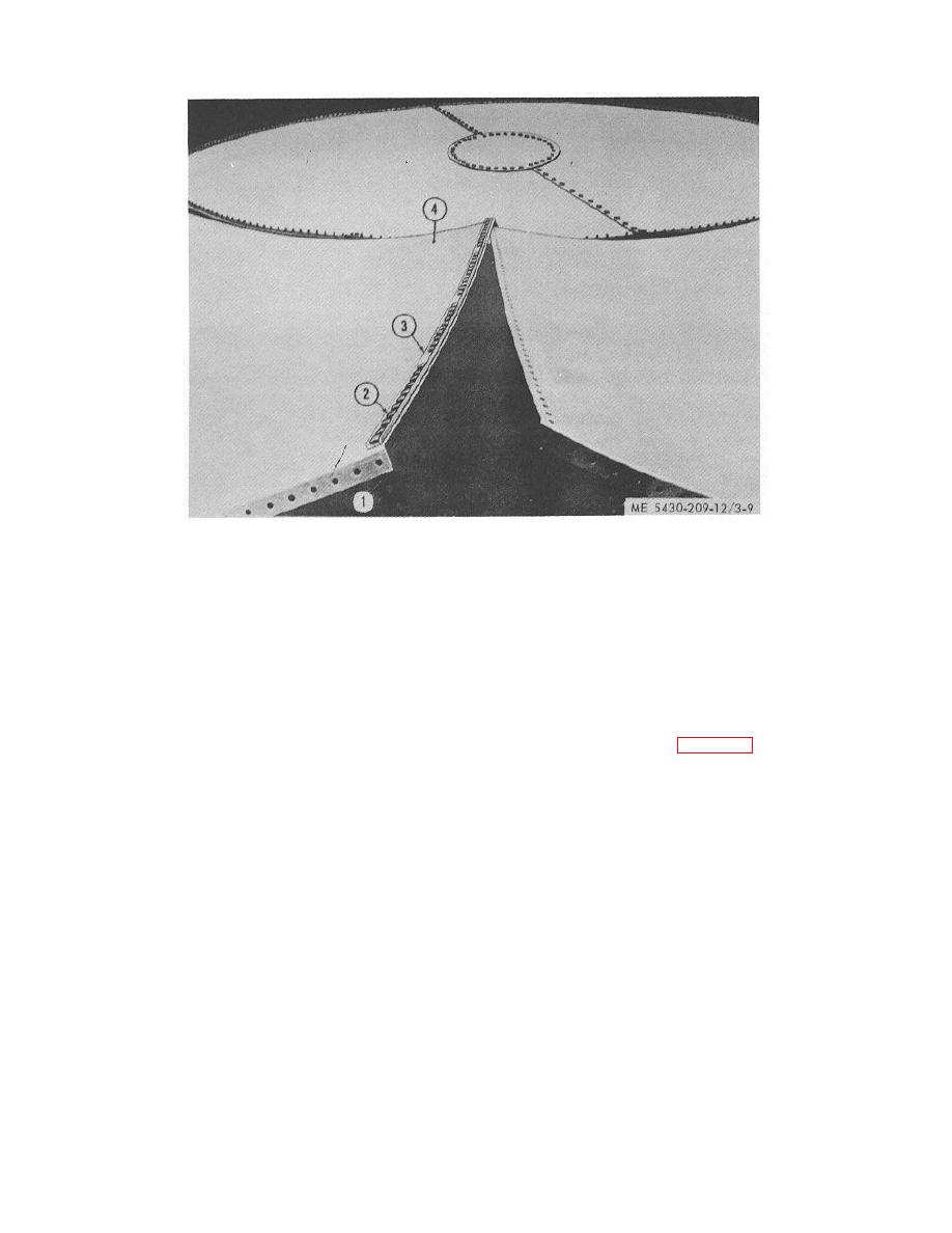
Figure 3-9. States with gasket, channel, and bolts assembled |
|
||
| ||||||||||
|
|
 TM 5-5430-209-12
1.
STRIP GASKET
2.
BOLT
3.
STAVE JOINT CHANNEL
4.
STAVE
Figure 3-9. States with gasket, channel, and bolts assembled.
bottom, the bottom must be raised to provide clearance
(c) Insert 1/2 -by 11/4 -inch bolts (2) through
for inserting and tightening bolts after installation of
stave joint channel (3), stave (4), and gasket (1), in that
staves.
order. Omit one bolt about 10 inches from the bottom
(a) Raise outer edge and block with short
and other bolts at about 2-foot intervals so that drift pins
lengths of timbers (1, fig. 3-10) at equally spaced
can be inserted to aline staves with one another before
intervals around the perimeter of tank bottom. Set
bolting them together.
(3) Preparing outer edge of tank bottom. Since
blocking about 6 inches from outer edge.
channels are not used on the outer edge (chime) of tank
3-9
|
|
Privacy Statement - Press Release - Copyright Information. - Contact Us |
