 |
|||
|
|
|||
|
Page Title:
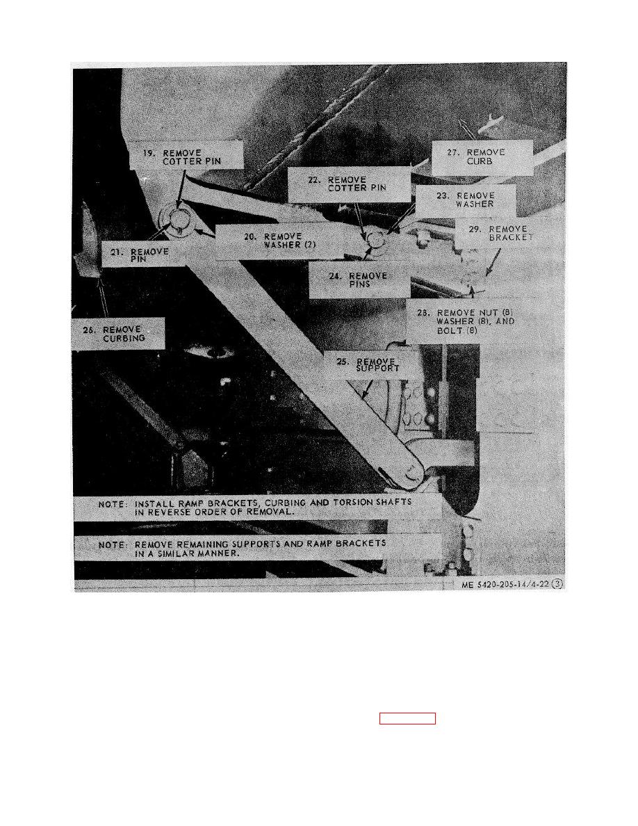
Figure 4-22. Curbing and torsion shaft, and ramp bracket, removal and installation. (sheet 3 of 3) |
|
||
| ||||||||||
|
|
 TM 5-5420-205-14
Figure 4-22. Curbing and torsion shaft, and ramp bracket, removal and installation. (sheet 3 of 3)
connection (locator) receives the male locator with the
4-30. Pin Assembly, Stepped Head, Female Tapered
taper guiding the section inward until secured about the
Locator, Replacement
inner pin; then it is locked in place by action of the
The interior bay has two female and two male locators
pinning cylinder. The inner pin of the female tapered
at each end; the end bay has two male and two female
locator is subject to wear, and may be replaced as
locators at the end opposite the yoke. These locators
shown in figure 4-23.
are used in conjunction with the ropes, capstan and bitt
to join transporter bridge connections. The female
4-31
|
|
Privacy Statement - Press Release - Copyright Information. - Contact Us |
