 |
|||
|
|
|||
|
Page Title:
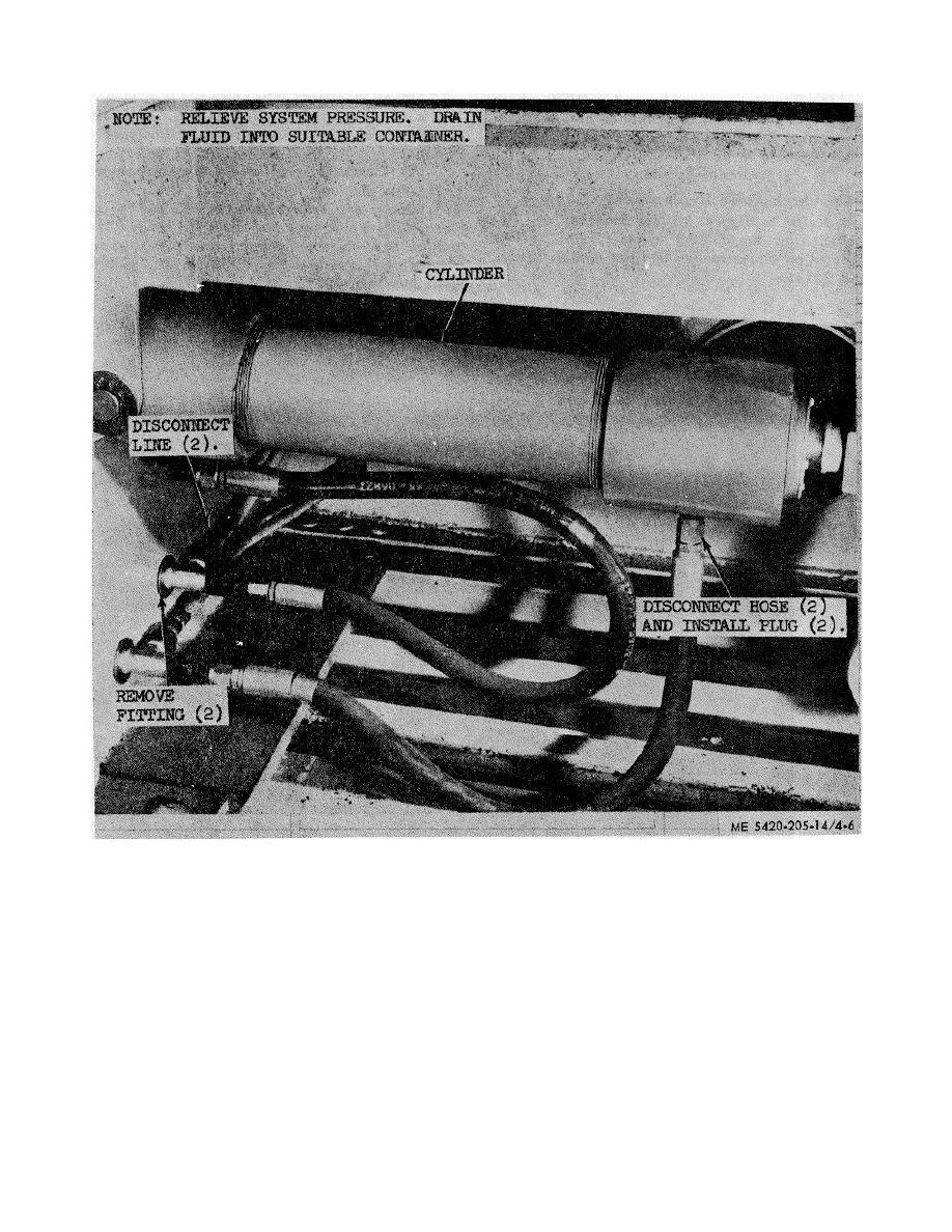
Figure 4-6. Typical line-hose cylinder application |
|
||
| ||||||||||
|
|
 TM 5-5420-205-14
Figure 4-6. Typical line-hose cylinder application
c. Hydraulic Hose. Hydraulic hose must be properly
more of these noses together in proper combination, any
hose or tube on the superstructure may be replaced in
installed by using correct length and type for pressure
an emergency. Removal and installation of hydraulic
system involved, with no twist from coupling to coupling,
hoses may be accomplished as follows:
as indicated by color code lines on hose. See TM 5-
(1)
Relieve all pressure from the system by
5420-204-12 for super- structure models 2195-1 and
2195-2, and TM 5-5420-210-12 for models 2271 and
gently unscrewing coupling nuts and allowing residual
2272 for correct tools to be used at installation to
pressure in the lines to escape.
prevent damage to coupling nuts. A kit containing
(2)
Drain the hydraulic system into a
various sizes and lengths of hose is furnished at
suitable container.
organizational level and is provided to enable
(3)
Disconnect coupling and cover or plug
emergency repairs to be made in the field, in event
line
failure of hose or tube occurs. By connecting two or
4-9
|
|
Privacy Statement - Press Release - Copyright Information. - Contact Us |
