 |
|||
|
|
|||
|
Page Title:
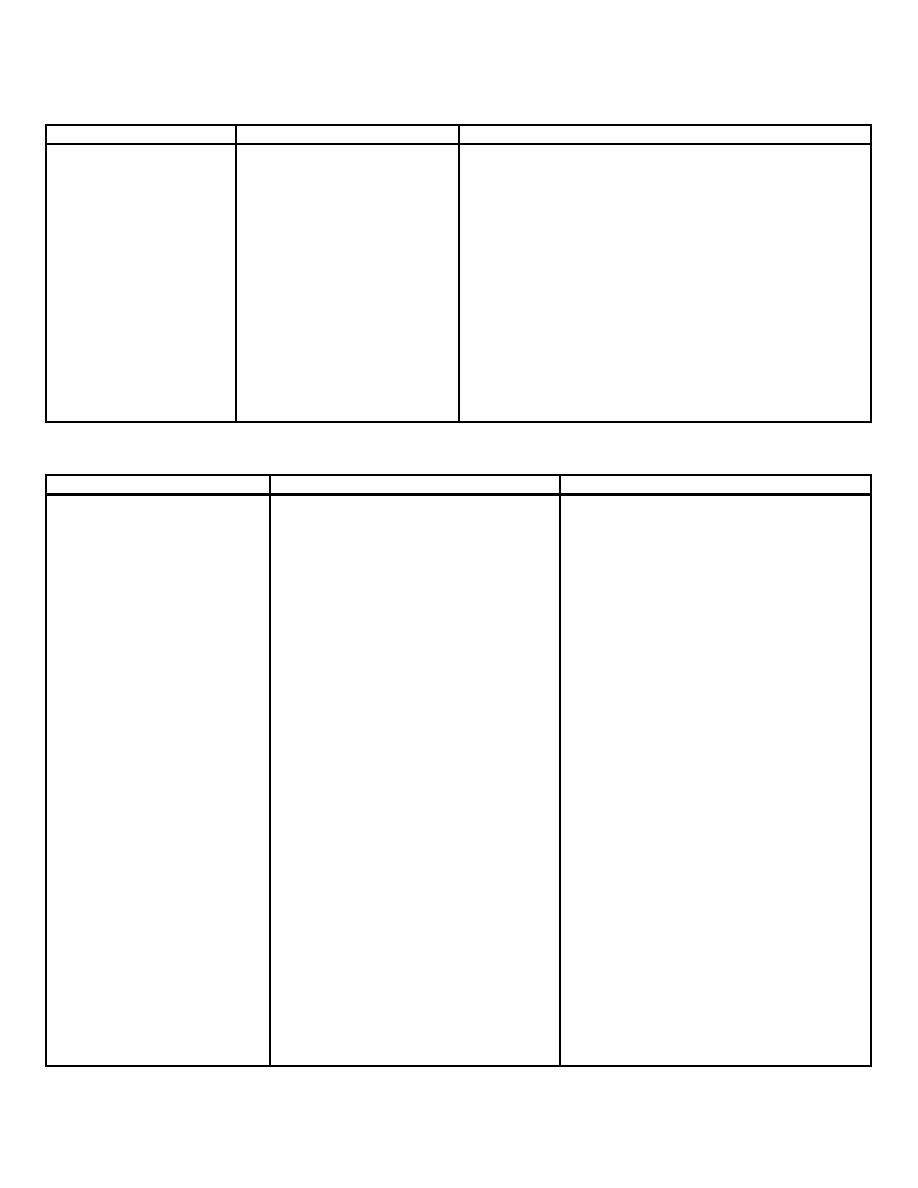
Table 3-5. Operator/Crew Controls, Monitor Control Panel SB-2600/G |
|
||
| ||||||||||
|
|
 TM 32-5895-227-14&P
Table 3-4. Operator/Crew Controls, Radio Intercept Control Switchboard (RICS) SB-2602/G - Continued
Control
Description
Function
SPEC ICOM - bottom
One alternate action
Push on for MULTIPLE INTERCOMMUNICATION
solenoid-held push-
of DFF position No. 2 using Telephone Set TA-
button switch.
676/G (SPECIAL) with INTERCOM, SPECIAL
OUTSTATION selected. Push again for off.
SPECIAL MONITOR -
Three alternate action
Push on for DFR position No. 1 to monitor special
top row
solenoid-held push-
outstations using Telephone Set TA-676/G
button switches.
(SPECIAL). Push again for off.
SPECIAL MONITOR -
Three alternate action
Push on for DFF position No. 2 to monitor special
bottom row
solenoid-held push-
outstations using Telephone Set TA-676/G
button switches.
(SPECIAL). Push again for off.
PHONES jack
Jack
Allows use of a headset and microphone for two-
way intercommunication with Intercom, Special
Intercom, and CCC position.
Table 3-5. Operator/Crew Controls, Monitor Control Panel SB-2600/G
Control
Description
Function
POWER ON
Two-position toggle switch.
Power on/off switch. Up for on; down for
off.
RECORDER 1and
Serves as power indicator. One or both ON
red lockout indicator lamps will light when
the
RECORDER 2 indicator lamps
recorders are in use and under control of
another outstation.
RCVR MONITOR - ON
Two-position toggle switch.
Up for on. Connects J6 receiver No. 1 and
J7 receiver No. 2 to monitor line.
RCVR MONITOR - PRTY 2 -
Two-position toggle switch.
Up for PRTY 2; down for PRTY 1. Selects
PRTY 1
J7 receiver No. 2 or J6 receiver No. I for
monitoring when RCVR MONITOR - ON
switch is on (up).
RECORDER IN - RCVR 1
Two-position toggle switch.
Up for on. Connects J6 receiver No. 1
signal to recorder input circuit. Down for
off.
RECORDER IN - RCVR 2
Two-position toggle switch.
Up for on. Connects J7 receiver No. 2
signal to recorder input circuit. Down for
off.
RECORDER 1 - ON and
Two single-action pushbutton switches.
When ON, button is pushed, ON button
RECORDER 11 - OFF
indicator lamp lights, and Recorder No. 1
starts.
When OFF, button is pushed, OFF button
indicator lamp lights, and Recorder No. 1
stops.
3-8
|
|
Privacy Statement - Press Release - Copyright Information. - Contact Us |
